Improving Aircraft Stall Characteristics
with Fixed Devices
Kate Bernard
AVI401 - Aerodynamics
Professor Steven Accinelli
April 25, 2003
Stalls and Spins
Stalls and resulting spins have caused aircraft accidents since the beginning of flight. Even though airplanes have evolved to have better stall characteristics, stalls and spins continue to be a leading cause of accidents (Landsberg).
A stall occurs when airflow separates from all or part of the upper surface of a wing, resulting in sudden loss of lift. This is caused by exceeding the critical angle of attack (angle of attack is the angle between the relative wind and the chord line of the airfoil). Below the critical angle, airflow over the wing surface is relatively smooth. Above the critical angle, the thin layer of air above the wing, or "boundary layer," becomes turbulent and separates from the airfoil (Dole and Lewis, 53). Lift is destroyed and drag increases, causing the aircraft to rapidly lose altitude. Pilots are trained to recover from this condition. However, if the stall occurs too low to the ground, there may not be enough altitude to recover. A study of aircraft accidents from 1992 to 2002 reveals that approximately 80 percent of fatal stall accidents occurred within 1,000 feet of the ground (Landsberg). Stalls are usually associated with slow flight in a nose-up attitude, but they can occur at any airspeed or attitude.
Spins are of even greater concern because recovery requires more altitude and more actions on the part of the pilot. Simply stated, a spin is an autorotation resulting from one side of the wing stalling more than the other. Spins cause rapid loss of altitude. If the pilot does not recover, the aircraft will spin into the ground. Aircraft design affects the ease of entering and recovering from spins. Adding devices to improve stall characteristics will generally reduce spin-related accidents; preventing a stall or making it gentler can reduce accidental spins. Straight-wing aircraft must stall before they will spin (swept-wing aircraft do not necessarily have to stall first) (Dole and Lewis, 186).
Favorable Stall Characteristics
Aircraft are designed to have the most favorable stall characteristics possible given the compromises involved. A good aircraft should give the pilot adequate warning of the stall, stall gradually, and tend not to spin after the stall (USCFC). This means the aircraft wing should stall at the roots first, rather than at the tips where the ailerons are located. (Stalling at the tips first renders the ailerons ineffective for roll control.) Usually a twist, or "washout," is built into the wings so that the tips are always at a lower angle of attack. However, this is not always enough to create good stall characteristics. Some aircraft require further modifications to the wing. In the interest of safety, several types of fixed devices can modify a basic wing in order to improve stall characteristics. These include winglets, leading edge cuffs, stall strips, stall fences, slots, and vortex generators.
Winglets
Winglets, which are vertical extensions of the wingtips, improve stall characteristics by reducing induced drag. This induced drag comes from high pressure air under the wings flowing around the tips to the lower pressure area above, creating vortices. Winglets redistribute the intensity of wingtip vortices over a larger area. They increase the maximum coefficient of lift, resulting in a lower stall speed (BLR, Inc.).


NASA studied the effect of winglets on the performance and handling qualities of aircraft. Using windtunnels, NASA tested two versions of a model airplane: one with winglets and one without. At stall, the airplane without winglets tended to "roll off" and "drop a wing" (Van Dam et al.). The airplane with winglets demonstrated improved stall characteristics. According to a NASA report, "The winglets appeared to prevent the wing tip from stalling firstÉ reducing the tendency to roll off" (Van Dam et al.). In another study during the fuel crisis of the 1970s, NASA aerodynamicist Richard Whitcomb found that winglets reduced drag by 20 percent (Larson). Less drag means faster stall recovery.
Winglets have disadvantages that may outweigh their advantages in some cases. They create interference drag at the junction between the wing and winglet. This drag offsets the induced drag reduction. Winglets also have a tendency to flutter (Larson).
Since the 1980s, winglets have become common on airliners and business aircraft. They are either built into the original wing design or retrofitted. The Airbus A319 and A320 have small upper and lower winglets. The A330, A340, and Boeing 747 have larger, conventional winglets. The Boeing Business Jet (BBJ) has "blended" winglets which curve up from the wing. Retrofitting a Beech Duke with winglets not only reduces stall speed, it has the advantage of moving that plane from IFR approach category B to category A (BLR, Inc.).
Leading Edge Cuffs
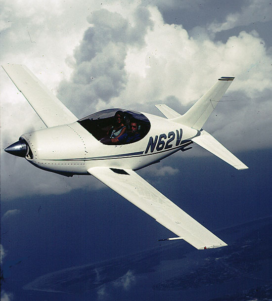
Leading edge cuffs are extensions that project forward and droop from the outboard sections of an aircraft's wings. They divide a wing into two different airfoils. The outboard section, with the cuffs, has a lower angle of attack and continues flying while the inboard section stalls. This allows the ailerons to continue to be effective in the stall. Wing cuffs also increase the stalling angle of attack (Preston).
The VariEze, a canard kitplane designed by Burt Rutan, was the first airplane to use leading edge cuffs after NASA testing. The aircraft did not have conventional stall characteristics. This was aggravated by the fact that builders often installed large engines that shifted the center of gravity too far aft. The aircraft tended to experience wing rock at stall, which is a rapid oscillation about the roll axis caused by one wing stalling, then the other, and so on (Hodgkinson 170). NASA equipped a model of the VariEze with wing cuffs and tested it in a windtunnel. The cuffs made the stall more benign. Burt Rutan was impressed, and nearly every VariEze builder afterward incorporated leading edge cuffs in their airplanes (Cox).


Leading edge cuffs also proved effective on the Questair Venture kitplane, which had poor stall/spin characteristics before the modification (Cox).

The Cirrus SR20 and SR22, which are modern production aircraft, have very distinct outboard leading edge cuffs. The inboard sections of the wings show warning signs of a stall while the outboard sections continue flying normally (Fallows 115).


The disadvantages of leading edge cuffs are that they complicate the wing design and cannot be easily added to an existing wing.
Stall Strips
A simple way to make the inboard section of a wing stall first is to install a stall strip on the inboard leading edge. Stall strips are lengths of wedge-shaped metal, wood, or other material that run parallel to the leading edge. At high angles of attack, the strips disrupt the boundary layer behind them and cause a stall in that area (Preston). They have the added benefit of causing a more pronounced stall buffet, providing more warning to the pilot.

Stall strips are very common, especially in homebuilt aircraft, because they are easily removed and reattached. Homebuilders can experiment by putting the strips in different locations and noting their effect on stall characteristics. Stall strips are also found on many production aircraft, such as the Mooney series and the Cirrus SR20 and SR22. Some aircraft use stall strips on only one wing in order to eliminate an asymmetric stalling pattern (Preston).


While stall strips often improve stall characteristics, they are not always a quick fix for an airplane with poor handling qualities. In July of 1997, NTSB Chairman Jim Hall wrote a letter to FAA Administrator Barry Valentine condemning the use of stall strips on the Piper Tomahawk. His letter suggests that stall strips did nothing to improve the stall characteristics of the Tomahawk:
"...[S]hortly after delivery of production airplanes began, owners and operators of the airplane complained that the lateral directional characteristics at the stall were abrupt and unpredictable, and that the airplane exhibited a rapid roll as the stall occurred. In 1979... Piper modified the wing design... by adding two additional stall strips. An airworthiness directive (AD 83-14-08) mandated that all existing airplanes be retrofitted with the additional stall strips.
"However, the additional stall strips may not have solved the problems with the stall characteristics. According to an August 1982 Aviation Safety article, 'Test pilots and flight instructors have found that both the two-strip and the four-strip Tomahawks have a tendency to drop a wing (as much as 90 degrees) in an intended straight-ahead stall if prompt and positive controls are not used" ("NTSB Letter").
Stall Fences
Stall fences are another device to prevent wing tips from stalling before the roots. They are thin plates which project up from the wing and lie parallel to the aircraft's axis of symmetry. Without these fences, a spanwise airflow along wings causes the boundary layer to thicken toward the wingtips, especially on swept-wing aircraft. This results in early boundary layer separation at the wingtips and loss of aileron control. Fences block spanwise airflow, preventing boundary layer buildup over the ailerons and thus improving stall characteristics (USCFC).

Stall fences are primarily found on swept-wing aircraft like business jets and fighters, but are also found on straight-winged general aviation aircraft.

The Eagle 150 has a unique design featuring a main wing, a forward wing, and a horizontal stabilizer. Each side of the main wing has a stall fence, which according to the manufacturer "redirects the airflow to the ailerons, creating a re-energizing effect.


This allows the pilot or student pilot full control at minimum speed, and even at the point of stall" (Eagle Aircraft).
 (Jurjur
  )
)
Some aircraft have aerodynamic stall fences. These are not the typical vertical plates, but instead other devices which create the same effect. The Questair Venture kitplane has a small vertical slot on the leading edge of each wing; the airplane looks like it ran into a bandsaw. At high angles of attack, air flowing through this slot creates a trailing vortex that acts like a stall fence. NASA found that this "rooster tail" of air creates turbulent, high pressure air that can "impede the spanwise advance of the stall" (Cox). The Cirrus SR20 and SR22 have a similar feature. According to the manufacturer, "At high angles of attack, two distinct leading edges create an aerodynamic stall fence that serves as an airflow barrier, preventing the stalled inboard portion of the wing from affecting the outboard portion still producing lift" (Cirrus Design Corp.).
Whether the stall fence is a physical plate or an airflow barrier, this device combats the progression of a stall across a wing and helps keep air flowing over the ailerons.
Slots
Fixed slots in aircraft wings are used to increase the maximum coefficient of lift and delay the stall. Slots are long holes near the leading edge of a wing that run parallel to the leading edge. At high angles of attack, slots route high pressure air near the stagnation region under the wing to the lower pressure region on top (Dole and Lewis, 56). This rerouted air energizes the boundary layer and delays its separation (USCFC). Slots allow the aircraft to reach a higher angle of attack before stalling (Preston).
Slots were one of the earliest boundary layer control devices. In 1917, German pilot G.V. Lachmann stalled and crashed his airplane. While recovering in his hospital bed, he thought of adding several parallel slots to a wing, somewhat like a Venetian blind. He eventually created a model and tested it. He applied for a patent in 1918. But patent authorities turned him down, saying that the slots would destroy lift. Meanwhile, British aircraft designer Handley Page experimented with several different arrangements of slots (even including slots running chordwise).


He found that adding leading edge slots to an aircraft could increase lift by 60 percent. Page and Lachmann learned of each other's experiments and successfully patented the leading edge slot (USCFC).
Slots greatly improve the performance of aircraft at high angles of attack, but they have disadvantages as well. They must be designed into the wing from the beginning; they cannot be retrofitted to improve a design. They cause a higher stall angle, so the plane must approach in a nose-up attitude that decreases visibility (USCFC). The main disadvantage is that slots create excessive drag during normal cruising flight (Smith 42). A solution to that problem is the slat, which is a slot with a moveable cover.
Vortex Generators
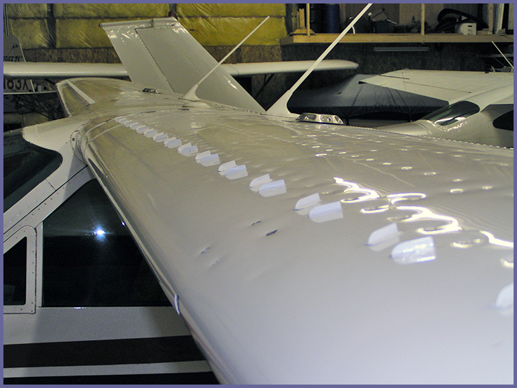
The most common boundary layer control devices are vortex generators. These are tiny plates mounted near the leading edge of the wing, perpendicular to the surface (USCFC). Vortex generators energize the boundary layer by mixing in high-energy air from outside the boundary layer (USCFC). They delay airflow separation (Preston).
Vortex generators are found on everything from small general aviation aircraft to large jets. They may be installed by the manufacturer or purchased as a retrofit. Micro Aerodynamics, Inc. offers vortex generator kits for the Cessna series. The kit includes 80 vortex generators for the wings that decrease the stall speed of the Cessna 172 by at least three knots (Micro Aerodynamics, Inc.).

Cub Crafters, Inc. produces a similar kit for the Piper Super Cub which includes 36 vortex generators. The kit compresses the boundary layer by approximately 60 percent and reduces stall speed by up to six miles per hour. The stall is also more docile since the airflow reattaches more quickly during recovery (Cub Crafters, Inc.).

Installing vortex generators are one of the easiest and cheapest ways to modify the stall characteristics of an airplane. A kit for a small aircraft usually costs approximately $1,500 and can be installed in one or two days.
Conclusion
The devices discussed in this paper can help warn the pilot of a stall, cause the airplane to stall more gently, and make the airplane resist spinning. They are added measures of safety that improve a basic wing. Small changes in airflow patterns over a wing can greatly improve aircraft handling qualities at high angle of attack.
http://www.airspeedalive.com/writings/s ... stics.html
Y ciertamente preferiría evitar al tocapelotas de turno, me temo que en este pueblo son muy pijoteros (para algunas cosas, luego los perros de razas agresivas van sueltos y sin bozal...
)


